
With the widespread adoption of variable frequency drives (VFDs) in industrial automation systems, variable-frequency speed regulation has brought significant advantages in terms of energy efficiency, operational efficiency, and control flexibility. However, the harmonic distortion introduced by VFDs has also become an increasingly important concern. Harmonics generated by VFDs can lead to excessive heating of transformers and power distribution lines, increased equipment losses, abnormal operation of capacitor-based power factor correction systems, and, in severe cases, interference with the normal operation of other electrical equipment.
Why Do Variable Frequency Drives Generate Harmonics?
Harmonics generated by variable frequency drives (VFDs) are primarily caused by current waveform distortion resulting from the nonlinear current draw of power-electronic rectifier devices. The reason why VFDs generate harmonics is mainly related to their internal rectification process. Due to their specific operating structure, namely AC input → rectification → DC link → inversion → motor, the three-phase AC power on the input side is converted into AC power. However, the power semiconductor devices in the rectifier do not draw current from the power grid continuously and linearly. Instead, they draw current in segments according to a specific conduction pattern. Therefore, the current drawn by the VFD from the grid side is not an ideal sinusoidal waveform, but exhibits significant waveform distortion.
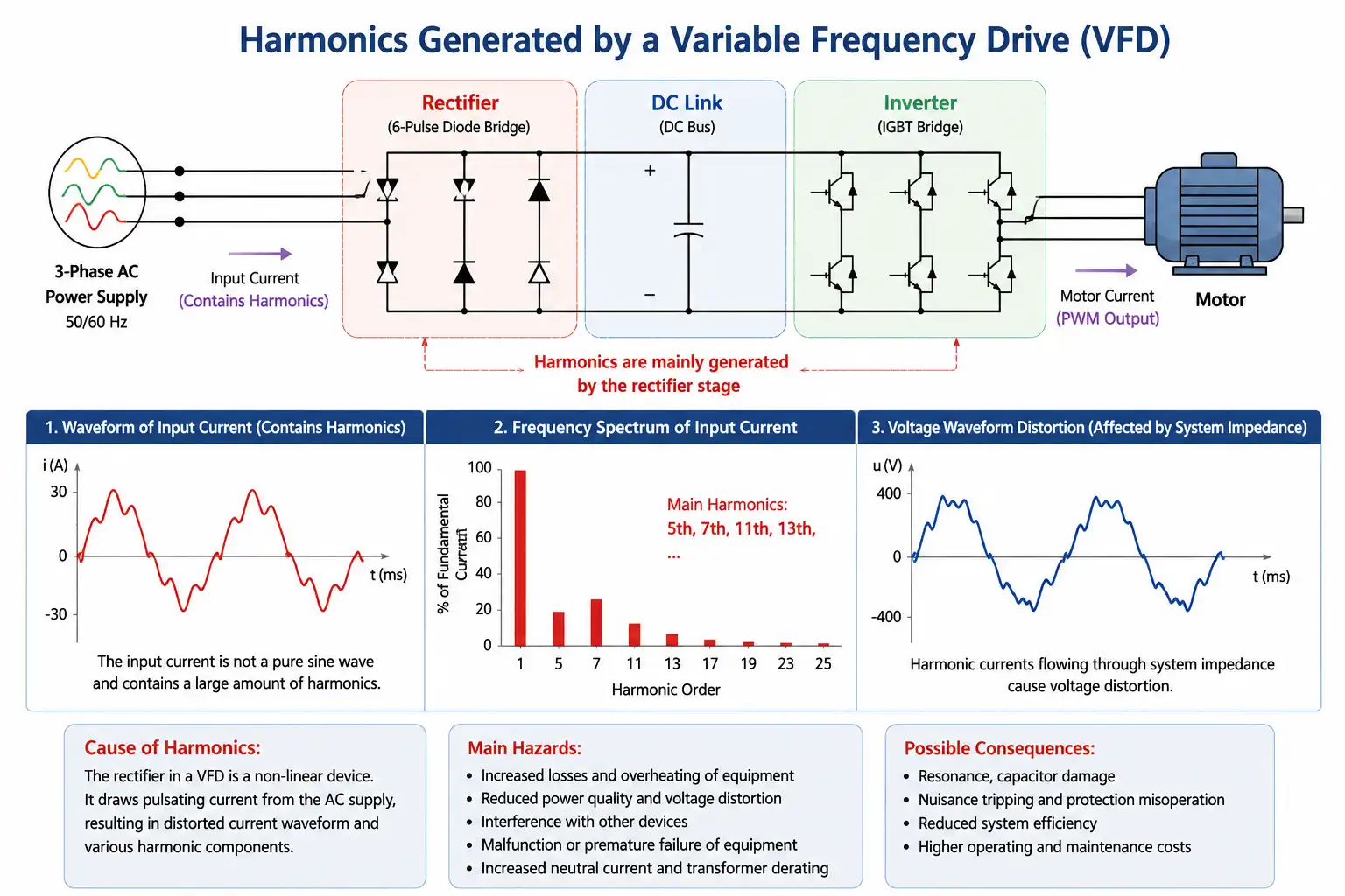
These waveform distortions generate different types of low-order harmonics, such as the 5th, 7th, 11th, and 13th harmonics. When a large number of VFDs are connected to the same power distribution system, these harmonic currents accumulate and, through the system impedance of transformers, power lines, and other components, generate harmonic voltages. As a result, the overall power quality of the power supply and distribution system is affected.
What Are the Adverse Effects of Harmonics?
The harmonic currents generated by VFDs can cause varying degrees of adverse effects on the power supply and distribution system as well as other electrical equipment. When the harmonic content exceeds the permissible limits of the system, it can have a significant impact on the distribution system.
- Increase losses in power lines and transformers, resulting in excessive heating of equipment and reducing its service life.
- Affect the compensation performance of capacitor banks, increasing the risk of resonance and amplifying harmonics at certain frequencies.
- Damage other sensitive and precision electrical equipment, as harmonic voltages may cause abnormal operation or malfunction of the system.
- Degrade the power quality of the power supply and distribution system, thereby affecting the safety and reliable operation of the power distribution system.
Harmonic Mitigation Methods and Solution Selection
Harmonic mitigation for VFDs should not rely on a single standardized solution. Instead, the appropriate approach should be selected based on the specific application and the actual operating conditions of the power distribution system. Before implementing mitigation measures, an on-site power quality assessment should be conducted to measure harmonic currents, harmonic voltages, and load characteristics. The root causes and severity of harmonic distortion should then be analyzed to determine the appropriate mitigation strategy.
Harmonic Mitigation Solutions
For a single VFD or a small number of low-power drives, an AC line reactor on the input side or a DC-link reactor can be used. By increasing the equivalent impedance of the rectifier circuit, improving the input current waveform, and reducing current ripple, these devices can effectively reduce harmonic current to a certain extent. This approach is simple and cost-effective, making it suitable for applications with relatively low harmonic levels and moderate mitigation requirements.
For systems with well-defined and concentrated harmonic components and relatively stable loads, passive harmonic filters (PHFs) can be applied. The filter is designed to target dominant harmonics, such as the 5th and 7th, by providing a low-impedance path for specific harmonic currents and thereby reducing their impact on the grid.
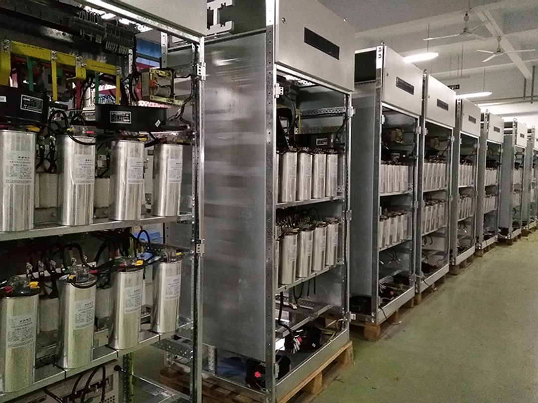
For multiple VFDs operating under frequently varying loads, where harmonic currents fluctuate significantly with operating conditions, an active power filter (APF) is generally more suitable. An APF continuously detects harmonic components and rapidly generates corresponding compensation currents, enabling dynamic tracking and compensation of multiple harmonic orders. It therefore provides better adaptability to complex and highly fluctuating loads.
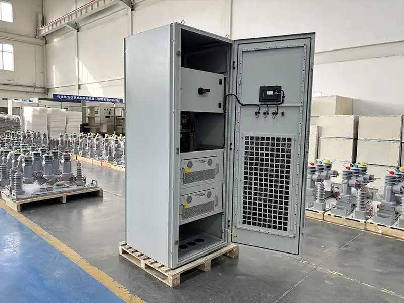
For high-power VFD systems, particularly in new installations, harmonic mitigation can be addressed at the system-design level by adopting advanced rectifier topologies, such as 12-pulse or 24-pulse rectification, or an active front end (AFE). These technologies reduce harmonic current at its source by improving the input current characteristics of the drive and are particularly suitable for high-power drive systems with stringent power quality requirements.
Harmonic Mitigation Solution Selection
In general, the mitigation strategy should be matched to the capacity, operating characteristics, and harmonic profile of the VFD load:
- Low-power drives / low harmonic levels: AC or DC reactors for source-side suppression.
- Stable loads / dominant characteristic harmonics: Passive filters for targeted harmonic filtering.
- Multiple drives / fluctuating loads / complex harmonic spectra: APFs for dynamic harmonic compensation.
- High-power or new drive systems: 12-/24-pulse rectification or AFE for source-level harmonic mitigation.
The selection of a specific solution should not be based solely on VFD capacity or quantity. On-site power quality measurements should be used as the primary basis for system design. Key parameters should include total harmonic distortion of current (THDi), total harmonic distortion of voltage (THDu), individual harmonic current components, and load profiles, together with transformer capacity, system short-circuit capacity, power distribution topology, VFD ratings and quantity, and load variation range.
Therefore, the recommended engineering approach is: measure first, analyze second, and design accordingly. This ensures that the mitigation system is properly matched to actual site conditions and avoids improper equipment selection or unsatisfactory mitigation performance.