
In power systems, the fundamental frequency of AC power is typically 50 Hz. In addition to the fundamental component (50 Hz), if periodic components at frequencies such as 100 Hz, 150 Hz, and 250 Hz are present in the voltage or current waveform, these components, whose frequencies are integer multiples of the fundamental frequency, are referred to as harmonics. Specifically, 100 Hz, 150 Hz, and 250 Hz correspond to the 2nd, 3rd, and 5th order harmonics, respectively.
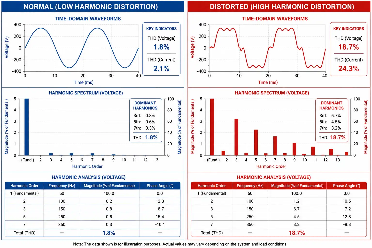
Harmonics are primarily generated by nonlinear loads, such as variable-frequency drives (VFDs), rectifier systems, switch-mode power supplies (SMPS), uninterruptible power supplies (UPS), and various other power electronic devices. The current waveforms drawn by these devices are not ideal sinusoidal waveforms. Their nonlinear characteristics result in waveform distortion, which in turn introduces harmonic components into the voltage and current of the power system.
When the harmonic content in a power system becomes excessive, it can cause significant voltage and current waveform distortion, thereby degrading power quality. Excessive harmonics may also result in additional heating and increased losses in equipment such as transformers, cables, and motors. In severe cases, they can lead to maloperation of protection devices, abnormal equipment operation, and other operational issues.
Therefore, harmonic monitoring, analysis, and mitigation are essential measures for maintaining the safe, stable, and efficient operation of power systems and ensuring high-quality electrical power supply.
How Are Harmonics Measured?
Harmonic measurement primarily involves the acquisition and analysis of voltage and current signals in a power system to determine whether harmonic components are present in the voltage and current waveforms, as well as to evaluate the magnitude and distribution of individual harmonic orders. In practice, professional test equipment such as power quality analyzers and harmonic analyzers is typically used for harmonic measurements.
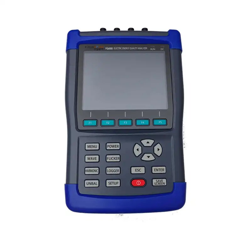
During the measurement process, the test instrument must first be connected correctly according to the voltage level, wiring configuration, and measurement requirements of the system under test. The instrument then acquires the voltage and current waveforms at the measurement point. Once the signals have been acquired, the instrument performs frequency-domain analysis of the sampled time-domain waveforms. Techniques such as the Fast Fourier Transform (FFT) are commonly used to decompose the measured waveform into the fundamental component and individual harmonic components of different orders.
Based on the analysis results, the magnitude, harmonic content, phase angle, and other parameters of individual harmonic orders—such as the 2nd, 3rd, 5th, and 7th harmonics—can be evaluated separately. This provides a detailed understanding of the characteristics and distribution of harmonic components within the power system. In addition, the overall harmonic level can be assessed using Total Harmonic Distortion (THD). In general, a higher THD indicates a greater degree of distortion of the voltage or current waveform relative to an ideal sinusoidal waveform.
From an engineering perspective, the essence of harmonic measurement is to use professional instrumentation to acquire voltage and current signals, apply frequency-domain analysis to extract individual harmonic components, and then evaluate the harmonic level and overall power quality of the power system based on parameters such as individual harmonic magnitudes, harmonic content, and THD.