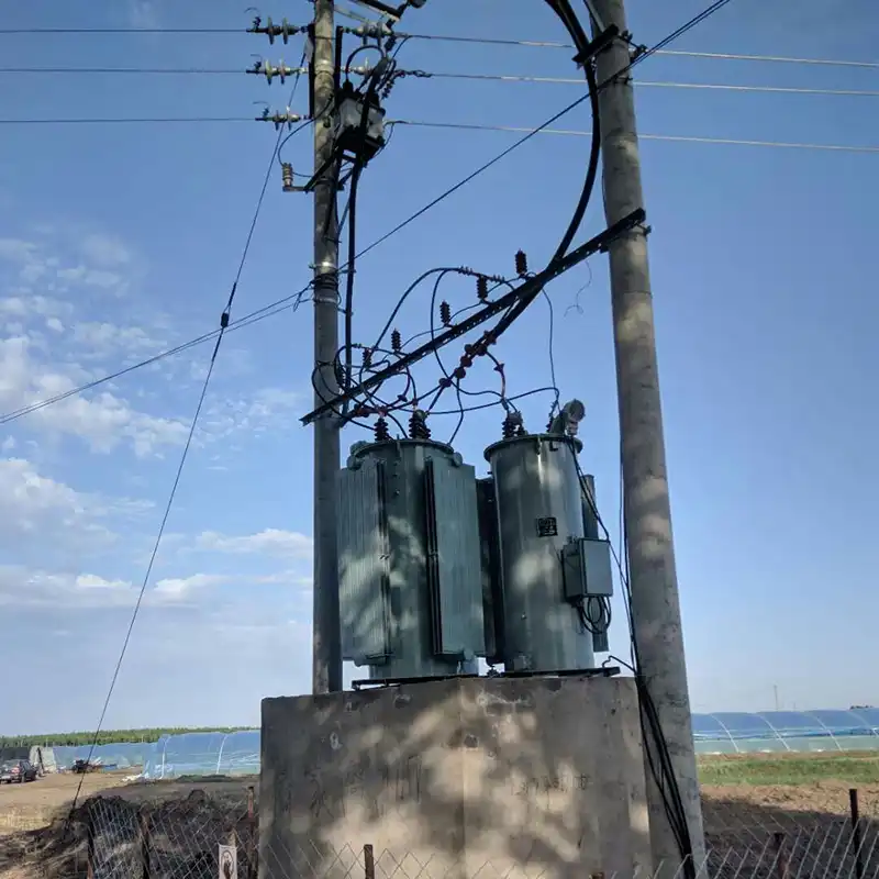
Single Phase Step-Voltage Regulators for Utility Distribution Systems
Step voltage regulators used in utility distribution systems are typically medium voltage mechanical automatic voltage regulators (AVRs). It is important to distinguish between the two types of AC automatic voltage regulators: medium voltage (mechanical) and low voltage (mechanical or electronic). These types have different operational and design characteristics, making their applications distinct. Low voltage regulators are designed to protect end-user equipment from overvoltage and undervoltage conditions, whereas medium voltage regulators are primarily used by power companies to compensate for voltage drops in feeders or distribution systems.
Basic Operation of Step Voltage Regulators
A step voltage regulator is essentially a transformer with a high voltage winding (shunt) and a low voltage winding (series) that can be connected to either assist or oppose their respective voltages. The output voltage can thus be the sum or difference of the winding voltages. For instance, with a transformer that has a turns ratio of 10:1 and 1000 V applied to the primary, the secondary voltage will be 100 V. This configuration makes the transformer an autotransformer, capable of stepping up (boosting) or stepping down the system voltage by 10%.

By changing the connection from the shunt to the series winding (via a commutation switch) and automatically adjusting the tap to vary the turns ratio, the system voltage is regulated to the desired level. This adjustment is managed by microprocessor-based and/or mechanical controls within the automatic voltage regulator, which dictate when and how to change the tap. Modern controllers also include data acquisition and communication capabilities for remote applications.
Step voltage regulators typically offer a voltage adjustment range of ±10% of the input line voltage, divided into 32 steps of 5/8% (0.625%). This provides 16 steps each for stepping down and stepping up the voltage (5/8% x 16 steps = 10%). Utility AVRs can be installed on feeders or substation buses and can be either single-phase or three-phase units. In utility applications, it is more common to use three single-phase units connected in configurations such as grounded star or closed delta, due to the typically unbalanced construction of utility distribution lines and the presence of single-phase loads. This setup helps maintain better phase voltage balance compared to a single three-phase unit or ganged operation. Additionally, many open-delta regulator banks are installed on lightly loaded three-phase feeders, which require only two regulators and are more cost-effective than a full three-phase bank.
Voltage regulators in utility distribution systems operate relatively slowly, with a time delay of at least 15 seconds, making them unsuitable for applications where voltage varies in cycles or seconds. Utility step voltage regulators are mainly used to boost voltage on long feeders where the load changes gradually over several minutes or hours. The voltage band typically ranges from 1.5 to 3.0 V on a 120-volt base. The control settings can maintain voltage at a point down the line from the feeder by using the line drop compensator capability, resulting in a more stable average voltage and preventing overvoltages for customers near the regulator.


