Overhead outgoing signal type remote fault indicator
- Monitor the operating status of distribution network lines
- Collected fault alarm information
- Real-time statistical analysis data
- Locate line fault points
This product is suitable for neutral grounding, arc suppression coil grounding and small resistance grounding systems, applied to 6~35kV overhead lines. JJYW-BC overhead outgoing signal type remote transmission fault indicator is installed on the overhead line of 6~35kV, which is composed of acquisition unit and collection unit.
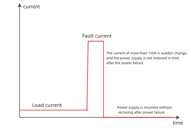
According to the characteristics of short circuit, the fault is judged by measuring the sudden change of current and its duration by electromagnetic induction method. A fault detection device that automatically ADAPTS to the change of load current and is only related to the short-circuit current component when fault occurs; No need to set the setting value, automatically adapt to the load current and substation line protection setting, to avoid large load fluctuations, closing surge current under the situation of misoperation.
The main criteria for action
First, the normal load current is greater than the power-on threshold value (default 3A) and remains for more than 30 seconds;
The sudden change of short-circuit current is greater than 150A (configurable), and the duration is greater than 40ms (configurable) and less than 3s;
Finally the switch trips and the current drops below 2A.

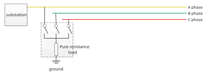
The method of external application signal detection is adopted. When the ground fault occurs and the zero voltage exceeds the set threshold, the external signaling device starts and injects characteristic current signals into the fault line; When the fault indicator of the fault line detects the characteristic current signal, the fault indicator gives a flip indicator and uploads it to the master station system.
External source and external signal type fault indicator are only suitable for single power supply systems. In the event of a ground fault, the external signal source superimposes a load between the normal phase and the fault phase (ground phase), so that the two form a loop, so that the characteristic current signal is injected into the grid, and this signal can only be detected before the fault point, and disappears after the fault point.

The external signal source is generally installed at the outlet of the substation line. When the line is normal, the signal source does not operate. When the ground fault occurs, the external signal source detects the presence of zero sequence voltage and identifies the ground fault. The external signal source performs a series of operations, and finally injects characteristic signals into the power grid through the non-fault phase of the cutting gate.
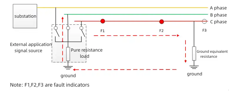
Taking the ground fault of phase C as an example, when the non-fault phase (take phase B as an example) is closed by the external signal source, the BC phase is looped through the ground. A current is generated in phase C, from the substation outlet to the ground fault, flows into the ground, and flows through the ground back to the external resistance load inside the signal source, and finally reaches phase B. Therefore, both F1 and F2 fault indicators can detect characteristic current signals between the substation and the ground fault point. After grounding the fault point, the F3 fault indicator will not detect the characteristic current signal, so it will not flop action.

Therefore, it can be determined that the fault point is between F2 and F3.
If you are attracted to our products, please send us a message and we will contact you as soon as we receive it. Email: [email protected] Whatsapp:+8613653737638