Power Factor Correction Solutions
A poor power factor due to induction motors, transformers, and other inductive loads can be corrected by connecting suitable capacitors. A poor power factor caused by distorted current waveform is corrected by adding harmonic filters. The process of creating the magnetic field required by an inductive load causes a phase difference between the voltage and the current. A capacitor corrects the power factor by providing a leading current to compensate the lagging current. Power factor correction capacitors are designed to ensure that the power factor is as close to unity as possibe. Although power factor correction capacitors can considerably reduce the burden caused by an inductive load on the supply, they do not affect the operation of the load. By neutralizing the magnetic current, capacitors help to cut losses in the electrical distribution system and reduce electricity bills.
To discourage energy wastage, some electricity distribution companies penalize consumers with a power factor that is below a specified value, and offer an incentive to consumers with a good power factor (usually above 0.95). This encourages consumers to install power factor correction equipment in their electrical systems. Benefits of adding power factor correction capacitors to electricity networks include reduced losses, improved voltage, increased system capacity, and reduced electricity bills. Key variables to consider when selecting capacitors for power factor correction include load type, load constancy, load size, load capacity, method of utility billing, and load starting methods.
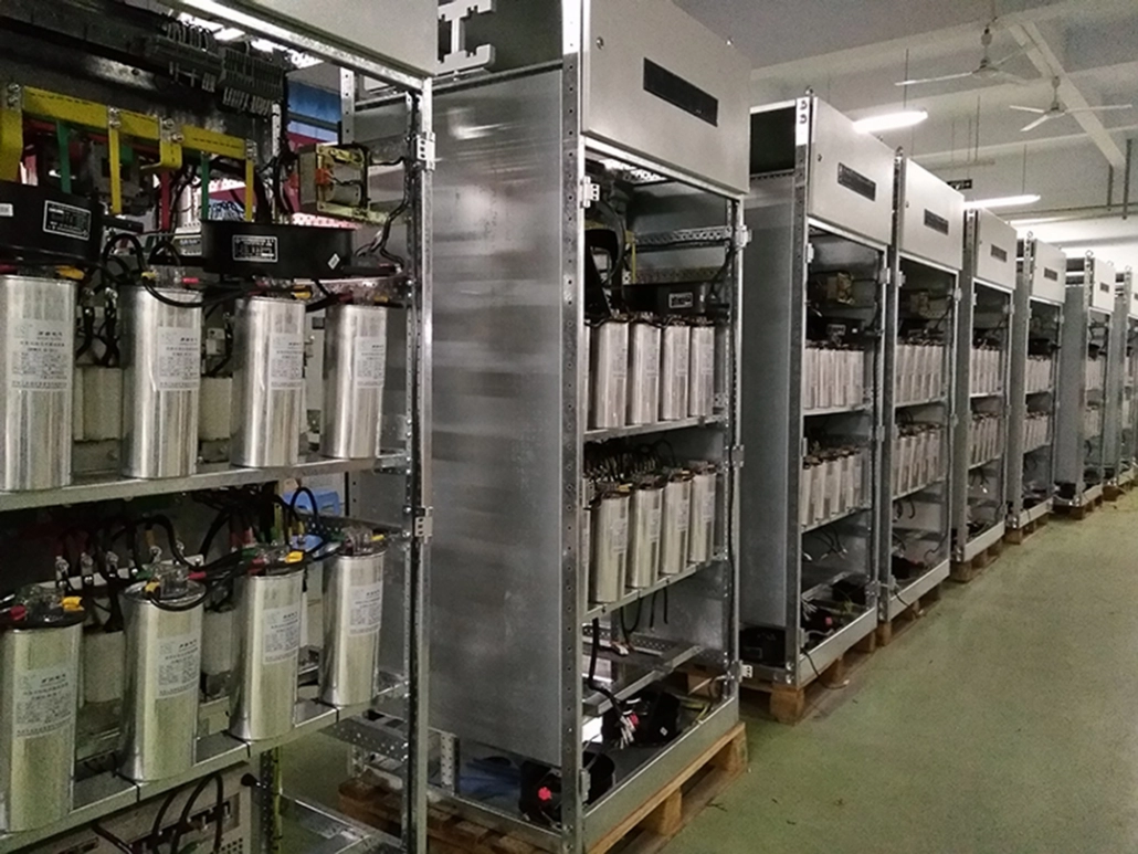
Power factor correction capacitors are usually installed as banks of capacitors when substations or large facilities are involved. In the case of sinusoidal or linear loads, they can be installed as individual capacitors that are easy to install or replace, and do not require separate switching. On the other hand, capacitor bank installations have lower cost per kVAR, and provide exact power factor correction capacitance when automatic switching systems are used.
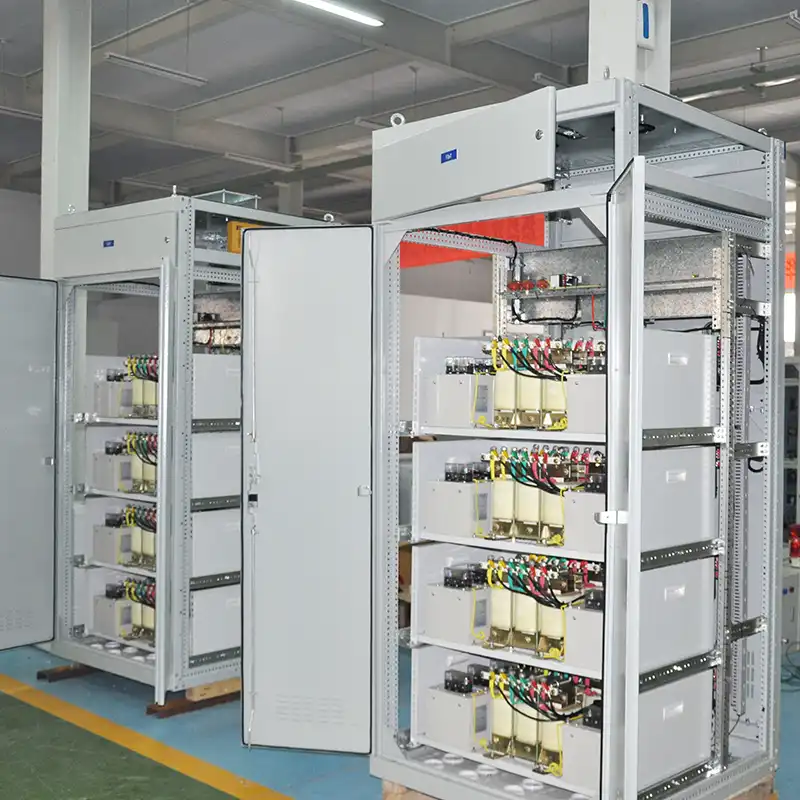
Depending on the needs of a particular substation or facility, fixed or automatically switched capacitor banks can be installed. A fixed power factor capacitor bank can be switched on when the inductive load is on, and off when the individual load is off. Such capacitors are energized only when power factor correction is needed. In facilities with multiple loads, load conditions and power factor correction needs change frequently. Automatic capacitor systems are suitable for such facilities. They prevent over-correction and under-correction.
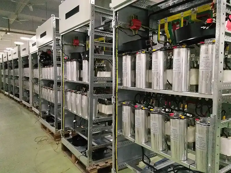
Large inductive loads such as oil drilling rigs, wind turbines, large motors, arc furnaces and auto crushes have dynamic load characteristics. Such large dynamic loads demand sophisticated automatic capacitor systems with fast response capabilities. Transient-free automatic capacitor banks are used for power factor correction in applications where large inductive loads are involved. Harmonics can significantly reduce the life of capacitor banks. For loads that produce harmonics, a harmonic filter should be added. This filter removes unwanted harmonic frequencies from the electrical system.
Inductive loads such as transformers, generators, motors, chokes, and arc welding equipment produce an electrical lag that results in current and voltage having different signs. The energy required to maintain magnetic reversals in inductive loads is referred to as reactive power. Reducing reactive power by improving the power factor of an AC load helps to minimize the overall cost of running inductive loads. Capacitors are commonly used in industries to improve the power factor and minimize energy wastage.

