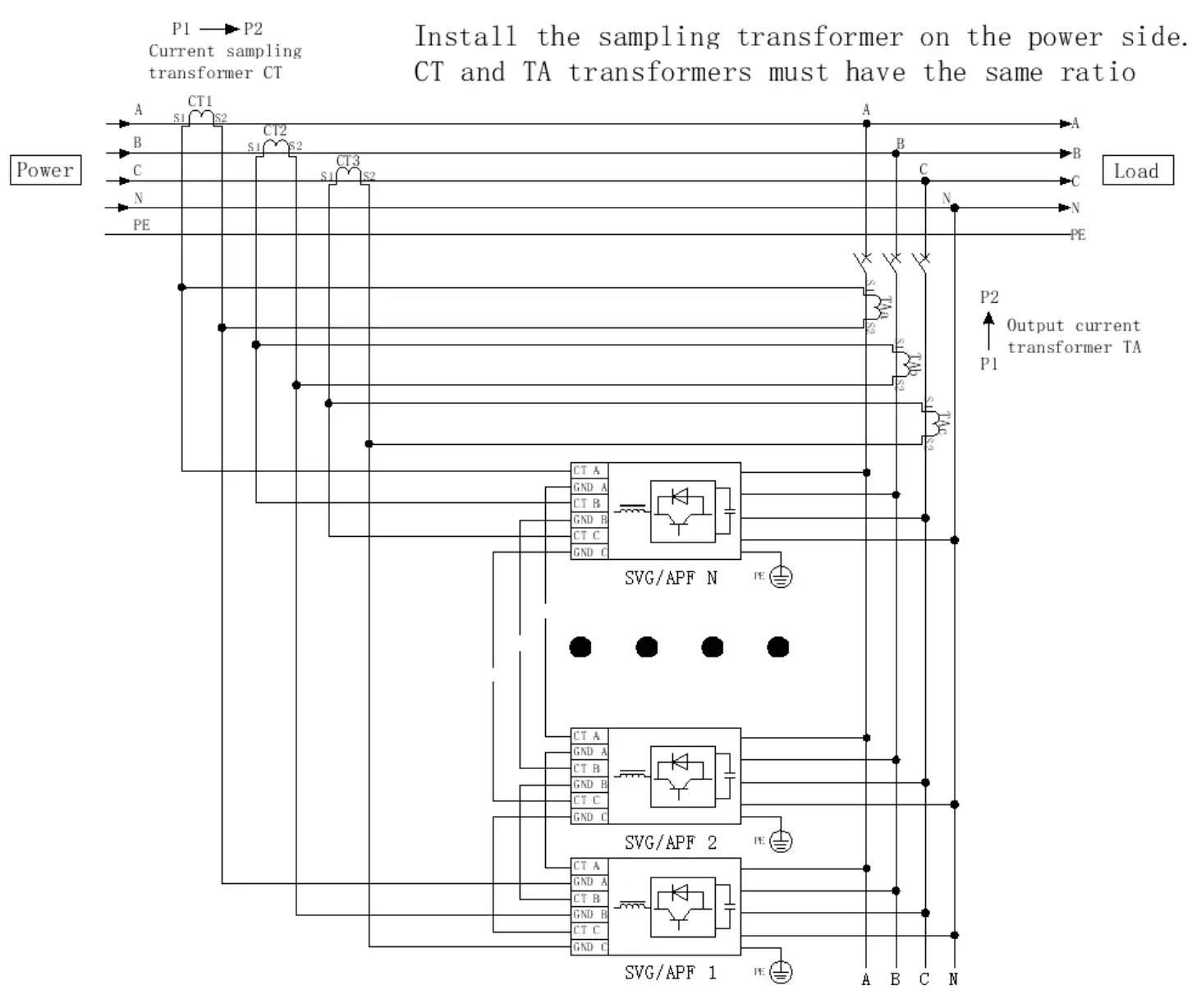
The proper selection of current transformers (CTs) is critical for maximizing the performance of active harmonic filters (AHF) and static var generators (SVG) in harmonic suppression and reactive power compensation applications. This guide outlines essential CT selection criteria for AHF/SVG systems while highlighting the advantages of multifunctional AHF/SVG modules and adaptable CT installation approaches.
Current Transformer Selection Criteria for AHF/SVG Applications
- Current Rating Requirements
The CT’s rated current must match or slightly exceed the electrical system’s maximum load current to guarantee precise harmonic current measurement and effective real-time monitoring.
- Accuracy Class Specifications
The CT accuracy class should be selected based on the AHF/SVG system’s compensation precision demands. For applications requiring high-accuracy harmonic measurement and dynamic compensation, CTs with superior accuracy classes (such as 0.2 or 0.5) are strongly recommended.
- Installation Configuration Options
Load-side installation (open-loop mode): Ideal for harmonic source identification and targeted compensation
Grid-side installation (closed-loop mode): Enables comprehensive system-level harmonic mitigation
The chosen installation location significantly impacts the CT’s wiring configuration and measurement accuracy, requiring careful consideration of the overall system design.
- System Compatibility Considerations
Proper system integration requires matching the CT’s electrical parameters with the AHF/SVG control module’s specifications. For instance, Strong Power’s solution incorporates modular design features that support multiple CT types through plug-and-play connectivity, facilitating quick installation and reliable operation via standardized interfaces.
Strong Power’s AHF/SVG module CT mounting options:
Strong Power’s AHF/SVG modules offer flexible CT installation configurations to accommodate diverse application requirements:

- Load-side Installation (Open-loop Mode)
- Configuration: CTs installed downstream of AHF/SVG units
- Advantage: Direct measurement of load-generated harmonic currents
- Application: Ideal for localized harmonic compensation scenarios
- Grid-side Installation (Closed-loop Mode)
- Configuration: CTs installed upstream of AHF/SVG units
- Advantage: Enables precise system-wide harmonic suppression
- Recommendation: Supplemental CTs should be installed at AHF/SVG output terminals for enhanced measurement accuracy
- Parallel Operation Solution
- Shared CT Configuration: Multiple parallel AHF/SVG modules can utilize common CT sets
- Advanced Measurement: For grid-side installations, supplementary output-terminal CTs are recommended
- Compensation Algorithm: The system calculates exact harmonic magnitudes through differential current analysis between primary and supplementary CT measurements
Technical Benefits:
– Dual-measurement capability improves harmonic detection accuracy by 15-20%
– Modular design supports both standalone and parallel operation modes
– Adaptive control algorithm automatically adjusts for installation configuration


