How are harmonics created and what are the benefits of harnessing harmonics?
Substation capacitors bank are primarily employed to supply reactive power and maintain busbar voltage levels. The total installed capacity of these capacitors is generally no less than 10% of the main transformer’s capacity, typically ranging between 10% and 30%. In accordance with the latest standards issued by the State Grid Corporation of China, the shunt capacitor capacity for 220kV substations should be between 10% and 30% of the main transformer capacity, while for 110kV substations, the range is 10% to 25%. Additionally, a power factor of at least 95% must be achieved under maximum load conditions.
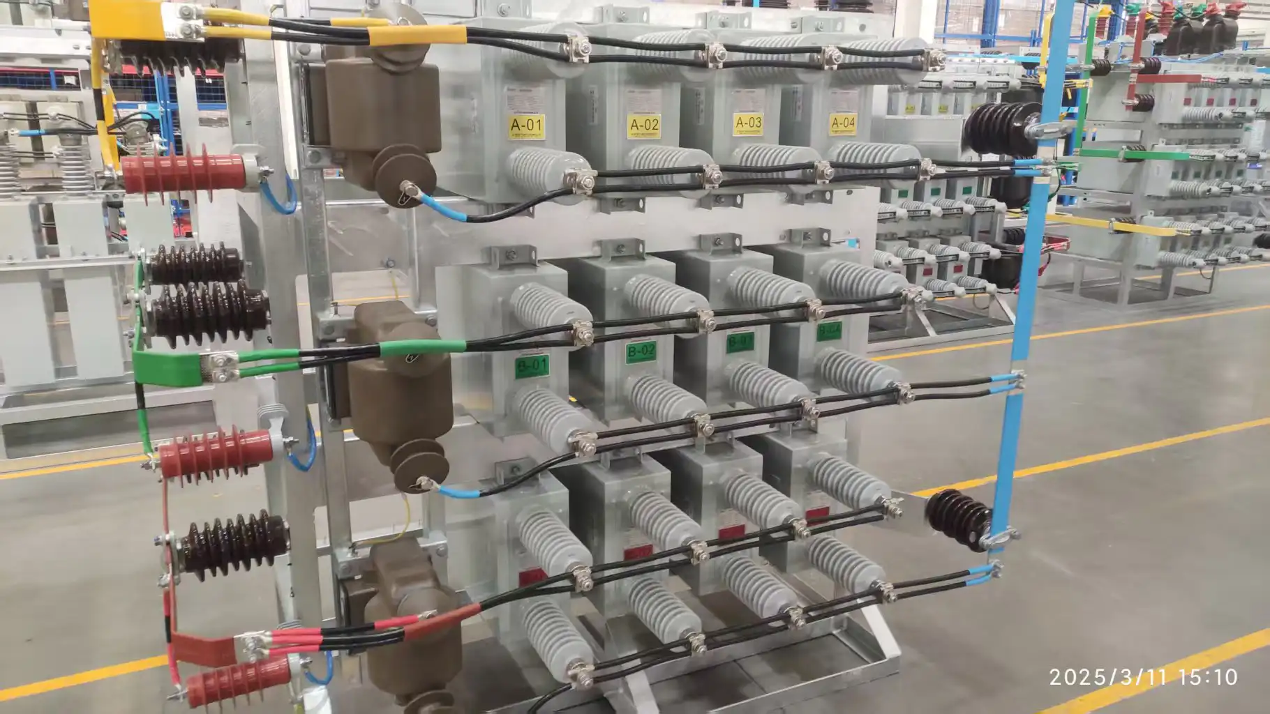
Advantages of Substation Capacitor Banks
Limiting Inrush Current
To suppress inrush current, a number of dry-type reactors are usually connected in series on the power supply side of the capacitor. Common protection configurations for capacitors—such as high-voltage shunt capacitors and static VAR compensators—typically include overcurrent protection, overvoltage protection, undervoltage protection, and differential voltage protection (unbalance protection).
Protection Mechanisms
Overvoltage and undervoltage protection monitor the busbar voltage. When the line voltage exceeds the set threshold, the capacitor bank is tripped after a time delay. Following a fault trip in an Automatic Voltage Control (AVC) system, the capacitor generally opens. To prevent maloperation of undervoltage protection when the potential transformer (PT) circuit breaker trips while current is still present, the undervoltage protection is latched. Overvoltage or undervoltage protection may also operate during bus voltage fluctuations caused by load impacts (e.g., railway traction shock). If equipment inspection reveals no abnormalities, the capacitor may be reclosed. A critical yet often neglected condition is verifying that the switch is in the off position. If the bus is de-energized while the switch remains open, the undervoltage protection may still operate. Some capacitor bank manufacturers do not incorporate switch position logic, leading to unnecessary confusion in fault information transmission during power interruptions.
Overcurrent Protection
Overcurrent protection monitors current transformer (CT) measurements within the bay. It trips when the fault current surpasses a preset value. This protection covers all equipment in the bay, including conductors, cables, disconnectors, and reactors. If the capacitor itself shows no fault, a thorough inspection of cables and other related equipment must be conducted before reclosing.
Unbalance Protection
Unbalance protection detects the voltage difference between two branches in each phase. A trip is initiated when the unbalance voltage exceeds the set limit. This type of protection reflects internal capacitor failures by comparing healthy and faulty units. The unbalance voltage signal can be obtained from the secondary winding of the discharge coil. It should be noted that secondary cables used for capacitor voltage differential protection are often installed outdoors, where insulation is prone to degradation. Therefore, secondary cable protection should be reinforced—for example, with insulating tape and protective sheathing.
Lightning Arrester and Surge Capacitors
Lightning arresters are installed on capacitor equipment to suppress switching overvoltages and are generally placed near the source side of the capacitor. Surge capacitors are also used to protect against transient overvoltages, enhancing the stability and service life of high-voltage shunt capacitors and static VAR compensators. These surge protective devices are vital for maintaining power system reliability and efficiency by mitigating voltage spikes.
Improving Power Factor
Large inductive loads—such as motors and transformers—consume reactive power, causing the current to lag behind the voltage and reducing the power factor. Capacitor banks generate capacitive reactive power, which compensates for the inductive reactive power, reduces the phase difference, and significantly improves the power factor.
Reducing Line and Transformer Losses
For the same active power, a lower power factor results in a larger current flowing through the line. Since line loss is proportional to the square of the current (P_loss = I²R), improving the power factor reduces the current substantially, thereby significantly decreasing copper losses in transmission lines and transformers.
Improving Voltage Quality and Stabilizing System Voltage
Reducing line losses also reduces the voltage drop along the line. By providing reactive power support, capacitor banks help raise the voltage level at load nodes—especially at the end of long feeders—preventing voltage sag due to reactive power deficiency.
Improving Grid Transmission Capacity
The capacity of transformers and transmission lines (apparent power S) is fixed. By compensating reactive power, the power factor is improved, allowing the system to deliver more active power (P = S × cosφ) within the same apparent power capacity.
Improving System Stability
By maintaining local voltage stability, capacitor banks help enhance system-wide voltage stability and prevent voltage collapse. In certain cases, they can also provide temporary support for power angle stability.

