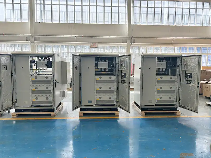
The Strong Power SVG System provides fast step-less compensation to correct leading and lagging power factor at a site. A poor power factor results in a phase angle difference between the current and voltage waveforms in an AC system. Improving power quality can reduce your energy costs, increase efficiency, and improve service life of infrastructure.
There are five steps in selecting the right SVG system for you.
This guide also includes breaker, cable and CT selection guides which is a critical part to the installation and operation of the system.
Step 1 – How much compensation is needed (kVAr)?
For existing site: To determine the amount of kVAr needed you will ideally have available the following information:
- Existing power factor
- Total load kVA
- New target power factor
This information may already be available via your electricity bill or can be requested from your energy retailer as part of your meter data. An Strong Power power quality audit can also be used capture the exact power factor for the site as well as for individual loads. This audit would also help capture any other power quality issues that may not be initially visible such as harmonic distortion or load imbalance.

The example below calculates required total compensation (kVAr) from the power factor (PF) value found on your electricity bill or meter data.
Sizing Tips:
If the required system is to correct a current PF of 0.75 to a new PF of 0.98, then the information required is as follows:
– Existing power factor = 0.75
– Total load kVA = 1333kVA
– New target power factor = 0.98
If the load power is 1000kW at a PF of 0.75, the displaced (reactive) power is 882 kVAr.
With the new target PF of 0.98, at the load of 1000 kW, the displaced (reactive) power is reduced to 203 kVAr.
The compensation SVG system size required to achieve this is:
882kVAr – 203kVAr = 679kVAr.
The total compensation in this case would need to be rounded up to the nearest 100th as the SVG system offered by Strong Power has modular increments of 100kVAr.
Therefore, the total compensation: 700kVAr.
Important note: Even though high kVAr can be a burden on the supply and electricity costs, inductive loads such as motors and welding equipment need some kVAr to maintain the electromagnetic fields required to operate.
For sites that are at the design/construction stage: The kVAr required can be calculated using tools such as PowerCad or vendor tools. Strong Power’s technical team can also assist with sizing up an appropriate system in accordance to the project details.
Step 2 – How much spare capacity do you need in the cabinet?
The power factor at a site can change with the type and number of loads that are running. If you plan to expand your site, add equipment, or replace existing products, accounting for spare capacity would be beneficial as a future-proof option.
The cabinet sizes are listed in the ordering guide, with incremental steps of 100 kVAr. The wall-mount systems can be expanded by connecting two systems in parallel.
Step 3-3 wire or 4 wire?
The four-wire option is required when there is an imbalance in the network.
Network imbalance is when differing line voltages across phases occurs, caused by unbalanced loads, single phase and phase-to-phase connections. This information can be found on your meter or power quality audit report.
| Use | Applicable industry examples | |
| 3 wire | For balanced networks | • Mining
• Industrial • Food and beverage • Manufacturing |
| 4 wire | For an unbalanced network with a fully rated neutral wire | • Commercial
• Office • Education • Shopping centers |
Step 4 – IP rating requirement:
The environment where the cabinet is installed significantly affects the required IP rating. Strong Power provides floor-standing cabinets with IP30 or IP54 ratings and a wall-mount module with an IP31 rating. However, none of these IP-rated cabinets should be installed outdoors in direct sunlight or exposed to rain without proper cover.
Step 5 – Colour of cabinet
Grey or Customizable


